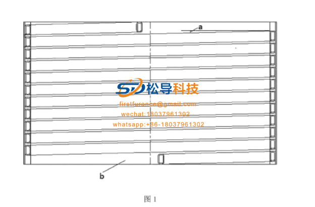
Currently, coreless induction melting furnace within the sensor by a spirally wound multi-way around the system, i.e., a rectangular copper tube wound along a helical path, as shown in FIG 1 FIG. However, the wound sensor has the following problems:
1 , the electric field can be converted to an effective magnetic field energy inefficient. Due to the spiral path, the path of the copper tube forms an angle a with the horizontal plane , and the magnetic field lines it generates are not completely perpendicular. This part of the magnetic field acting on the adjacent rectangular copper tube can be lost;
2 , spiral-wound at the head and tail ends occupied positions are separate one turn, i.e. part of the space is wasted (FIG. 1 in b shown here), can not interface with adjacent turns, the sensor and its nominal tonnage The height and the number of turns are determined. Since the position of one more turn is occupied alone, the height of the rectangular copper tube used for winding will decrease, the resistance value will increase, and the loss will increase;
Third, this spiral winding method has the same structure as the spring, so it will also exhibit elongation and contraction characteristics during use, increasing vibration, making the insulating material between the copper tubes easily fall off, resulting in insulating performance decline.
The utility model solves the above technical problems through the following technical solutions:
An inductor, characterized in that it includes a multi-turn copper tube coil formed after being wound on a reel, each turn of copper tube
The coils each include a horizontal winding section and a bending section, and the plane where each horizontal winding section lies is perpendicular to the axis of the reel
Straight, the horizontal winding sections of any two turns of copper tube coils are parallel to each other and have the same length, and the bending sections of any two turns of copper tube coils are
Parallel to each other and the same length. Due to the presence of the bending section, each turn of the horizontal winding section can be consistent with the axis of the drum
Maintain vertical, so the electromagnetic conversion efficiency is high. And the beginning and end of the sensor will not occupy a circle separately, the added copper tube
The average height of the coil can reduce the impedance of the inductor and reduce the energy loss of the inductor itself, and the inductor is no longer equipped
The structure of the spring has low vibration and improves the insulation performance. The copper tube of the copper tube coil is a rectangular copper tube. The cross section is circular or rectangular. There is a gap between two adjacent turns of copper tube coils, and the multiple turns of copper tube coils are fixed on a bakelite upright. Insulation material is provided in the compartment. It is characterized in that the coreless induction melting furnace includes the inductor as described above. Each horizontal winding section can be kept perpendicular to the axis of the reel, making the electromagnetic conversion efficiency high, and the beginning and end of the inductor will not occupy a single circle. The average height of the increased copper coil can reduce the inductor Impedance, thereby reducing the energy loss of the sensor itself, and the sensor no longer has the structure of the spring, the vibration is small, and the insulation performance is improved.
BRIEF DESCRIPTION

FIG. 1 is a schematic structural diagram of an existing sensor.

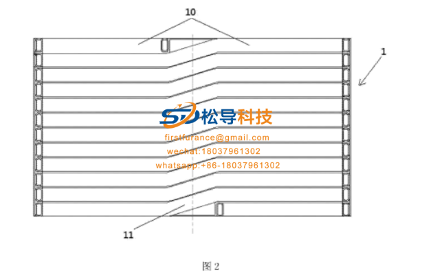
FIG. 2 is a schematic structural diagram of a sensor according to an embodiment of the present invention.

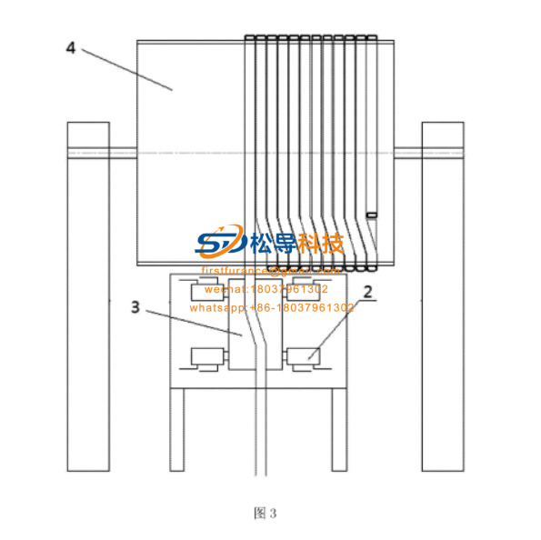
FIG. 3 is a schematic structural view of an apparatus for manufacturing an inductor according to an embodiment of the present invention.
The following is a preferred embodiment, and the present invention will be described more clearly and completely in conjunction with the accompanying drawings.
As shown in Figure 2 , including a multi-turn copper tube formed after winding on a reel
Coil 1 , each turn of copper tube coil 1 includes a horizontal winding section 10 and a bending section II , each horizontal winding section 10 is located
The planes are all perpendicular to the axis of the reel. The copper tube of the copper tube coil is a rectangular copper tube, and the cross section of the inductor is circular.
The horizontal winding sections of two turns of copper tube coils are parallel to each other and the same length, and the bending sections of any two turns of copper tube coils are parallel to each other
And the same length. The bending section is used to transition each turn of the copper tube coil to maintain most of the horizontal winding section and the reel
Vertical relationship, without forming an angle with the horizontal plane, only the bending section will have an inclined angle, relative to the existing
In the inductor, each turn of the copper tube coil is an obliquely wound structure. In this embodiment, the magnetic field that passes vertically through the object to be heated
The line of force increases, the magnetomotive force is large, and there is much useful work, so the electromagnetic conversion efficiency is high. Tests have shown that when electrical energy is converted into effective magnetic field energy, the conversion efficiency of the sensor of this embodiment is increased by about 7% relative to the existing sensor . In addition, for winding copper tube coils of the same number of turns on reels of the same height, the start and end of the inductor will not occupy a single turn, but the copper tube coil of the existing inductor will be occupied separately The distance given by one turn increases the average height of the copper tube, that is, the beginning and end of the copper tube coil are formed with a large utilization rate to form a turn of the copper tube coil perpendicular to the axis of the reel, thus making this embodiment The average height of the multi-turn copper tube coil is higher than the average height of the existing multi-turn copper tube coil, thereby reducing the resistance of the copper tube, so that the loss of the copper tube on its own heat will be reduced accordingly. Tests show that the energy loss of the sensor of this embodiment is about 16% lower than that of the existing sensor . Moreover, because the sensor maintains a vertical relationship with the axis of the reel, it no longer has the structure and characteristics of the spring, greatly reducing the telescopic characteristics, and the vibration is greatly reduced, so that the inter-turn insulation material will not easily fall off due to vibration, thereby improving Insulation performance. To further elaborate on the manufacturing process of the inductor, as shown in FIG. 3 , the hydraulic device 2 is used and the bending template 3 is used to make the turning angle of the copper coil of the adjacent turn. Winding on the reel 4 , after demoulding, according to the requirements of the distance between adjacent turns, that is, according to the requirements of different occasions, the distance between adjacent turns is required, the wound inductor is evenly pulled apart, and the bakelite column is installed to fix it. The turn is wrapped with insulating material.

