
1. Equipment description
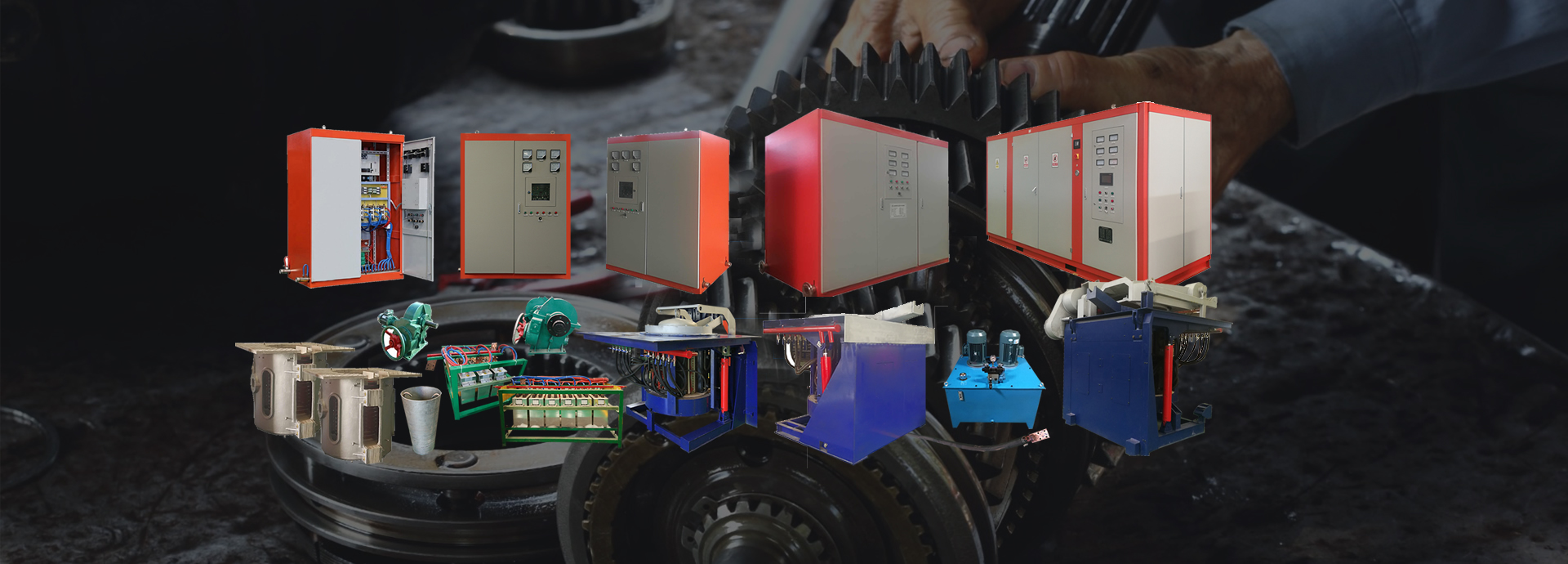
Equipment: 50 tons induction melting furnaces for foundry cast iron and steel melting work.
The induction melting furnace is a power-saving product, which has the characteristics of fast temperature rise, low energy consumption, stable and reliable operation, and the like. The service life of the complete equipment is designed and manufactured according to no less than 20 years, and the equipment control technology has been in the leading position in the industry for five years.
This induction melting furnace including 24-pulse rectifier transformer, a medium frequency power source , and two sets of steel furnace PLC auxiliary melting management systems and other components. PLC assisted melting management system, which can not only display real-time data and information of power supply operation, but also display the operating status and information of the entire system, and has automatic oven, cold furnace startup, fault diagnosis, fault information display and storage, operation information display , System status display and other functions.
Basic configuration: 24-pulse rectifier transformer ( rated capacity 20000kVA ), two sets of steel furnace, a medium frequency power supply, a set of inverters compensation capacitor, the power supply structure 12 to 24 Pulse bis parallel rectifier inverter structure. The tilting furnace is hydraulically flipped and equipped with a remote control box.
In the design of the equipment, give full consideration to the user's field work for the continuity of the state, the stove frequently the material, equipment selection for this program to ensure that production target users, and users must meet the general requirements for the device: Let equipment rugged and durable, Stable performance, safety and reliability.
2. Normal operating conditions of the equipment:
1. Environment:
a. The altitude does not exceed 1000m.
b. The ambient temperature is between 5 ℃ and 40 ℃.
c. The relative humidity is not more than 90% (at 25 ° C).
d. There is no conductive dust, explosive gas and corrosive gas that can damage metal and insulation.
e. No obvious vibrations and bumps.
2. Power requirements:
a. The main circuit supply voltage is 135 0V 50Hz, the fluctuation is not more than 5%, and the three-phase imbalance is not more than 5%.
b. Control system power supply voltage 380V, 220V, fluctuation is not more than 5%.
c. The supply voltage of the main circuit and the control system must be a sine wave, and the waveform distortion is not greater than 10%.
3. Water supply requirements:
The electrical part of the cooling water system uses a closed cooling tower . The closed cooling system does not need to dig a pool. On-site use only needs to connect the interface with the equipment to be cooled, without adding other auxiliary equipment. The water of the whole circulation system is soft water, the water quality is good, no scaling, and the closed circulation makes the water loss very small, and the equipment use and maintenance costs in the later stage can be greatly reduced.
I. Overview of 24-pulse rectifier transformer :
The pulse wave rectifier transformer is to reduce the pulsation coefficient on the DC side of the rectifier unit and the harmonic content on the AC side. Multiphase rectification must be adopted, which requires an artificial phase shift in the rectifier unit. Although there are many types of phase shifting, one method that is often used is to perform phase shifting on the grid side winding of the rectifier transformer. Generally, a single rectifier transformer is a 24-pulse wave, and many use low-voltage winding axial split structures. To achieve 24-pulse rectification, two 24-pulse rectifier transformers are usually used at the same time. There are technical problems such as increasing costs and wasting space.
1. Use a single 24-pulse rectifier transformer. Each phase has 4 coils, each transformer has a total of 12 coils, which can achieve 24 pulse rectification in one transformer, and the high-voltage voltage tap adopts the end voltage regulation structure, and leads with different turns of terminals at the coil end. The conductive rod is terminated at different positions to realize voltage tap conversion. A transformer can realize 24-pulse rectification, which saves costs and space on the site. The product has a simple structure, convenient operation and maintenance, stable performance, energy saving and energy saving, and long service life.
The advantages are as follows:
1. A set of switch cabinets can be omitted.
2. Compared with two transformers, it occupies less space.
3. Energy saving, a 24-pulse transformer has low loss and saves power.
4. Environmental protection, a 24-pulse transformer has less harmonics and more stable operation of the electric furnace.
ZSSP- 22000 / 10-1.5 * 4 rectifier transformer parameters:
Electric furnace capacity (t) | Intermediate frequency power (KW) | Transformer capacity (KVA) | Voltage combination | Connection group label | Impedance voltage (%) | |
Primary side (KV) | Secondary side (V) | |||||
50T | 20 000 | 22000 | 10 | 1500 | Y / d11 | 6 ~ 8 |
Second , the main technical parameters of 50T / 20000kw intermediate frequency coreless induction melting furnace
A. Comprehensive parameters | ||||
Serial number | project | Parameter requirements | ||
1 | Equipment form | IF melting furnace | ||
2 | Equipment use | For melting cast iron , carbon steel, etc. | ||
3 | Rated Capacity | 50T | ||
4 | Maximum capacity | 50T + 1 0% | ||
5 | Operating temperature | 1700 ℃ | ||
6 | Smelting material | Cast iron , carbon steel | ||
7 | Discharging method | Hydraulic : hydraulic control | ||
9 | Working noise | <85dB | ||
10 | Furnace structure | Steel shell | ||
12 | Melting rate | 50T / h | ||
13 | Melting power consumption | ≤ 52 0 ± 5% kW.h / t cast iron | ||
≤ 55 0 ± 5% kW.h / cast steel | ||||
14 | Melting time | 90 minutes / furnace | ||
B. Electrical parameters: | ||||
Serial number | project | parameter | ||
1 | Power | 25000kw / 12 phase 24 pulse 50T | ||
2 | Number of rectified terms | 24 pulses | ||
3 | Inverter | SCR parallel inverter | ||
4 | Rated frequency | 250 Hz | ||
5 | AC line voltage | 1500 V | ||
6 | IF voltage | 4500 V | ||
7 | Startup success rate | 100% | ||
8 | Power factor | Greater than 0.9 5 | ||
10 | IF Power | Circulating water flow | m 3 / h | 120 |
Inlet water temperature | ℃ | ≯35 | ||
Temperature rise | ℃ | ≯15 | ||
pressure | Mpa | 0.2-0.3 | ||
Furnace (dig the pool) | Circulating water flow | m 3 / h | 220 | |
Inlet water temperature | ℃ | ≯40 | ||
Temperature rise | ℃ | ≯20 | ||
pressure | Mpa | 0.25-0.3 | ||
C, furnace index | ||||
Serial number | project | 40 tons | ||
1 | Furnace shell structure | Steel or aluminum case | ||
2 | Furnace shell material | 45 # steel | ||
3 | Panel thickness | Thickness increases strength 20 mm | ||
4 | Yoke material | Z11-0. 3 | ||
5 | Yoke coverage | 8 5% | ||
6 | Yoke clamping | Stainless steel 1Cr18Ni9 | ||
7 | Cooling method of yoke | Double water cooling | ||
8 | Sensor copper tube material | T2 Pure Copper 99.9 | ||
9 | Sensor copper tube specifications | Wall thickness ≥ 8mm | ||
10 | Inductor turns | 22 turns on the main turn, 3 water-cooled turns on the top and bottom | ||
11 | Inductor insulation | 3 varnishes, double-layer bandaging, withstand voltage 8000V | ||
Inductor winding | Lengthened double parallel winding, machine winding (non-manual winding) | |||
Induction ring height | 2000mm x 2875mm | |||
12 | waterway | 16 in and 16 out , water connection hose | ||
13 | Outlet method | Test line | ||
14 | Water cooling ring material | Copper tube | ||
15 | Furnace shell heat | <75 ℃ (except for furnace bottom and furnace cover) | ||
1 6 | insulation | Coils and yokes are insulated with double layers of mica board | ||
17 | Refractory cement | GROUT 563A United States-Tianjin United Mineral Products | ||
18 | bolt | Common carbon steel bolts are grade 8.8. Other bolts made of stainless steel or copper | ||
19 | Crucible mold thickness | > 5mm | ||
20 | Waterway connection hose | Using non-flame retardant high-insulation rubber tube | ||
twenty one | Water trap | Stainless steel | ||
1 | Hydraulic pump | Double pump double electric | ||
2 | Unit type | Vertical | ||
3 | Hydraulic Components | Yuci or domestic famous brand | ||
4 | Guaranteed tilting angle | 0 ~ 95 ° | ||
3 . Constant power digital frequency power supply Description:
Digital frequency power supply is introduced first I six generation, except in the design of the main circuit only two conventional control circuit and the transformer to a control circuit board. The contactor, intermediate relay, and other auxiliary circuits are completely removed, so that the entire set of equipment is connected very little. Moreover, the advantages of three-phase AC input do not need to distinguish the phase sequence, and the intermediate frequency output line does not need to distinguish the phase, which makes it easier for users to debug on site .
Features of our company's IF power supply:
l constant power control system (highly integrated control circuit)
l Constant power thyristor intermediate frequency power supply system is an intelligent controller developed by our company. It is mainly composed of regulator, phase shift controller, protection circuit, start-up calculation circuit, frequency tracking, inverter pulse formation, pulse amplification and power drive. After digitization, it becomes a special chip, which is specially used for the control of thyristor parallel inverter IF power supply.
l Inverter control refers to the advanced control technologies from the United States such as ABB, Ajax, and Fuji Electric. The self-developed inverter control technology has strong anti-interference ability.
l board to board digital integrated control panel, digital trigger, high reliability, high precision, easy to debug, and other characteristics of non-relay element, length of work without the temperature drift, the operating point stabilization.
l Have perfect multi-level protection (water pressure, phase loss, under voltage, over current, over voltage, off time, through, operation interlock, etc.)
lstart-up method is an advanced frequency-sweeping type, which stimulates zero-voltage start-up, so that the operator can achieve 100% successful start-up without selecting a start-up voltage and start-up frequency.
l Adjust and match according to the load change, increase the melting and heating speed and save electricity (10%).
lhas the following meter indications: output voltage meter, output power meter, working frequency meter, intermediate frequency ammeter, power factor meter, input voltage meter, ground leakage meter and fault warning indication. (The electricity meter is installed between the transformer and the IF power cabinet)
l Power-on performance: Reliable start-up performance (regardless of no load or full load). The power supply uses a zero-voltage automatic frequency sweep start method and has frequent start functions. Whether under heavy load or no-load conditions, the startup success rate is guaranteed to be 100%.
l heavy load, reduce the commutation angle, relatively increase the voltage and reduce the current to make the power supply work close to the optimal value (rated value). At light load, increase the commutation angle, and relatively reduce the voltage and increase the current to make the power supply work. Near optimal value (rated value)
l characteristics——The intermediate frequency induction equipment uses a parallel resonance electric furnace. In the parallel resonance load, when the values of the inductance L (inductor) and compensation capacitor are determined, the natural frequency of its resonance is also determined. With the load (inductor) impedance The natural frequency also changes with the change of the frequency. When the empty furnace is lightly loaded, the frequency is lower; when the full furnace and cold material are heavy, the frequency is higher.
lup frequency tracking characteristic--During the startup process, when the startup frequency is closest to the load frequency, the startup success rate is higher. And the frequency changes with the load. Here, the frequency sweep starting method is adopted, that is, a set of frequency starting equipment including a range of load load frequency changes is sent, which is not affected by the load change, and thus the reliability of startup is greatly improved. As shown below.
l Use series compensation line to reduce the loss of the transmission line. In order to reduce the loss on the intermediate frequency transmission line, the compensation capacitor of the inverter is connected to a series voltage doubler. This connection method can double the voltage on the electric furnace than the inverter output voltage. In this way, under the same output power, the output current becomes 50% of the original, so that the loss on the IF transmission line is reduced to 1/4 of the original.