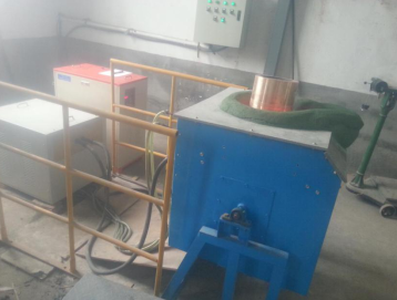
Uses: for melting copper powder, copper wire, copper scrap, copper block, copper, copper electrolytic copper melting furnace, copper was melted, the molten copper, the molten copper strip, the molten brass, the molten copper, the molten copper foil device,

1, IF copper melting furnace equipment selection table
KGPS | copper | Input voltage | Melting timemin |
SD - 7kw | 2KG | 220v | 10min |
SD -15 kw | 10KG | 380v | 10min |
SD -25 kw | 20KG | 380v | 20min |
SD Z-35 kw | 40KG | 380v | 30min |
SD Z- 45kw | 60KG | 380v | 30min |
SD Z- 70kw | 100KG | 380v | 30min |
SD Z- 90kw | 120KG | 380v | 40min |
SD Z- 110kw | 150KG | 380v | 50min |
SD Z- 160kw | 200KG | 380v | 60min |
2 , medium frequency copper melting furnace configuration:
Serial number | name | unit | Quantity |
1 | Medium frequencypower supply(KGPS) | station | 1 |
2 | Capacitor compensation box | station | 1 |
3 | Electric overturningfurnace | station | 1 |
4 | Split connection cable | One | 1 |
5 | Output water cooled cable | set | 1 |
6 | control box | One | 1 |
3 , customer self- installed machine accessories ( circulation cooling system ) :
1. Three-phase air switch 400A 1 ;
2. Power connection soft cable 90 mm2 several meters;
3 . Cooling tower 30 tons 1;
4. Pump 3.0kw/ head 30-50 meters 1 set ;
5 , equipment inlet and outlet water pipes: high pressure enhanced water pipe outer diameter 16 mm, inner diameter 12 mm several meters
6. Water pump inlet and outlet water pipe: 1 inch (inner diameter 25 mm) with wire high pressure reinforced pipe several meters
4, IF copper melting furnaces steps:
1, electrical connection: access to a dedicated power supply line, respectively, three-phase air switch. Then connect the ground wire. ( Note that the three-phase electric power should be able to meet the use of the equipment, and the wire thickness should be used according to the instructions )
2 , water: (depending on continuous working time and workload) select the cooling water system to achieve water circulation cooling.
3 , water: open the waterway, and check the water outlet of each device to see if there is water outflow, whether the flow and pressure are normal .
4, power: the power switch to open the control, followed by a switch to open the air behind the machine, and then turn the power switch on the control panel.
5 , start: Before the first furnace starts, the heating power potentiometer should be adjusted to the minimum as much as possible, and then slowly adjusted to the required power after starting. Press the start button to start the machine. At this time, the heating indicator on the panel lights up, and the prompt sound of normal operation and the work light flash simultaneously.
6. Observation and temperature measurement: In the heating process, it is mainly determined by visual inspection when to stop heating.
7. Shutdown: Shutdown, the control device switches off first, then turn off the main power external switch, then delayed until about 1 hour after the furnace temperature down; then off equipment cooling water, the heat inside the machine to facilitate the induction loop and the heat distributing .
8. In areas where it is easy to freeze in winter , it should be noted that after each use, compressed air should be used to blow out the water in and out of the equipment to prevent internal cracking of internal fittings and water pipes.
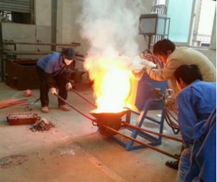
5 , customer molten copper scene picture:


