How are induction melting furnaces classified? How to choose an induction melting furnace ?
Induction melting furnaces have been widely used in factory production. According to the frequency of current, induction melting furnaces can be divided into three categories: high frequency and power frequency. High-frequency induction melting furnaces are mainly used in experimental research rooms due to the high current frequency and small capacity of the crucible . In the production of factories, they are mostly used with power frequency induction melting furnaces . According to the structure of induction melting furnace , it can be divided into induction melting furnace and cored induction melting furnace . Considering the current frequency used, it can be divided into medium frequency induction melting furnace , power frequency induction melting furnace and cored induction melting furnace . The current frequency used by the induction melting furnace is power frequency, so it is also called power frequency cored induction melting furnace .
1. Induction melting furnace
The induction melting furnace is used for the smelting of steel, iron and non-ferrous metals. The furnace manufacturer has serialized induction melting furnaces and can provide complete sets of equipment including power supply. The parameter table of induction melting furnaces lists the technical parameters of several commonly used induction melting furnaces for melting steel and iron , which can be selected by users. For reference, the technical parameters of each manufacturer may be slightly different.
The structure of the induction melting furnace with a furnace capacity of less than 250 kg is relatively simple, and there is no magnetizer. The furnace shell is made of aluminum alloy and divided into two halves. The middle pad is made of asbestos cement board, which is connected by bolts to form a circular aluminum shell; induction coil It is wound by a rectangular pure copper tube, a brass stud is welded to the coil, and a brass nut is used to connect the coil and the column together. A certain gap is left between the turns of the coil, and air is used for insulation between the turns. The outer surface of the coil is coated with moisture-proof paint. The whole induction coil is fixed on the aluminum shell through the two ends of the column. The tilting of the furnace is that the motor drives the furnace body to rotate after passing through the reducer.
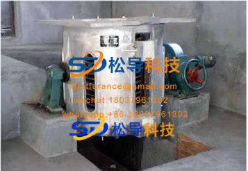
250 kg induction melting furnace
Induction melting furnace parameter table
Capacity kg | 150 | 250 | 500 | 1000 |
Current frequency Hz | 1000 | 1000 | 1000 | 1000 |
Rated power kW | 100 | 160 | 250 | 500 |
Voltage V | 700 | 700 | 700 | 700 |
Sensor voltage V | 700 | 700 | 1400 | 1400 |
Rated temperature ℃ | 1600 | 1600 | 1600 | 1600 |
Melting rate ( kg/h) | 130 | 200 | 380 | 750 |
Crucible : inner diameter x height /mm | Φ255 X400 | Φ300 x 500 | Φ 5 00 x 560 | Φ 500 x720 |
Coil: inner diameter X height /mm | Φ400 x 450 | Φ450 x 580 | Φ 560 x 650 | Φ700 x 800 |
Coil turns / turn | 17 | 15 | 19 | Parallel 12 + 12 |
Cooling water consumption / (t/h) | 5 | 7.5 | 10 | 18 |
The main part of the furnace lining is a crucible , which is generally smashed with refractory materials, but iron crucibles are used when melting low melting point alloys such as aluminum and zinc , which have higher melting efficiency and high power factor of the inductor.
Crucibles rammed with refractory materials generally use acidic linings, mixed with quartz sand and boric acid, and then dry rammed. Some factories use alkaline linings for some special requirements, such as solving the problem of cracks in complex castings. Generally, magnesia is used ( Mg >85% ) , its refractoriness is about 2000 ℃ , it can resist alkaline slag, and slag-making materials can be added in the furnace to remove phosphorus and sulfur. In the furnace surface part, because the refractory material cannot contact with the molten metal and is well sintered, 2% -3% water glass is often added .
Regarding the furnace capacity, 500kg induction melting furnace, there is also a steel structure for the furnace shell, the coil is provided with a magnetic conductor, and the tilting of the furnace body adopts a hydraulic drive.
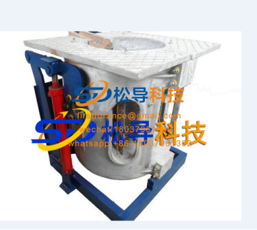
For a 1T induction melting furnace with a furnace capacity, the furnace shell is generally of steel structure, with magnets around the coil, and the furnace body is tilted by hydraulic transmission. Figure 12-74 shows an induction melting furnace with a furnace capacity of 1000kg. There is also an induction melting furnace with a furnace capacity of 1000 kg. The furnace shell is made of aluminum alloy. There is no magnetization around the induction coil, but the tilting of the furnace body uses hydraulic transmission. Figure 12-75 shows such a furnace. Compared with the two, the furnace capacity is under the same conditions. Of course, the induction melting furnace with a steel structure and a permeable magnet has a high cost, but its advantage is that the furnace has a strong structure and is safe and reliable to use.
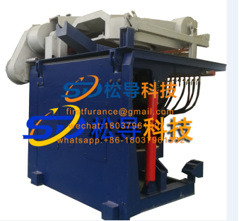
Figure 12-74 Steel shell induction melting furnace
In order to improve the melting rate of induction melting furnaces , some furnace manufacturers have introduced fast melting furnaces , which means that the input power to the inductor is increased, the melting time of the metal is reduced, and the melting rate of the furnace is increased, but the melting is increased. The electricity consumption per unit of metal. Table 12-17 lists some technical parameters of induction melting furnaces for rapid smelting .
Table 12-17 Technical parameters of fast melting furnace
Capacity kg | 150 | 250 | 500 | 1000 |
Current frequency Hz | 1000 | 1000 | 1000 | 1000 |
Rated power kW | 160 | 250 | 400 | 800 |
Voltage V | 700 | 700 | 700 | 700 |
Sensor voltage V | 700 | 700 | 1400 | 1400 |
Rated temperature ℃ | 1600 | 1600 | 1600 | 1600 |
Melting rate / ( kg/h) | 150 | 250 | 500 | 1000 |
Cooling water consumption / (t/h) | 5 | 7 | 10 | 18 |
For the furnace body structure of the induction melting furnace with a relatively large furnace capacity , see the figure . The coil pressing device uses a spring to fasten the coil from the top of the coil; the magnetizer is installed on the periphery of the coil to prevent magnetic flux leakage in order to save energy and at the same time The magnetic conductor strongly supports the coil from behind, which enhances the stability of the coil and resists the expansion force of the furnace lining; the induction coil is wound with a rectangular pure copper tube; the insulation layer of the coil is insulated by glass tape, and the whole coil is dried by dipping; According to production needs, acidic, alkaline and neutral lining materials can be used for dry furnace building; the detection device for furnace leakage , if a furnace leakage occurs, an alarm will be issued before the liquid metal reaches the coil. The tilting of the furnace body is driven by a hydraulic cylinder.
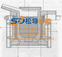
Schematic diagram of furnace structure
1 a furnace cover 2- coil pressing device 3 - magnetic conductor 4 - induction coil
5— Insulation layer 6 — Furnace lining 7 — Leakage detection device
The induction melting furnace used for melting non-ferrous metals has the same structure as the induction melting furnace for melting steel , except that the technical parameters are somewhat different, and the materials used in the crucible are different. The non-ferrous metal melting crucible useful for refractory ramming junction, is also useful graphite crucible , for the smelting of lead, zinc, magnesium, aluminum and aluminum crucible made of cast iron plate.
Table 12-18 Aluminum melting furnace
Rated Capacity t | rated power kW | Rated frequency Hz | Melting rate (t/h) | Operating temperature ℃ | Inductor voltage V | Power frequency incoming line Voltage V | Cooling water consumption |
(t/h) | |||||||
0.3 | 160 | 1000 | 0.2 | 780 | 700 | 3N-380 | 5 |
0.5 | 250 | 1000 | 0. 35 | 780 | 1400 | 3N-380 | 8 |
0. 8 | 350 | 1000 | 0. 53 | 780 | 1400 | 3N-380 | 12 |
1 | 500 | 1000 | 0. 8 | 780 | 1400 | 3N-380 | 15 |
1.6 | 750 | 1000 | 1.25 | 780 | 2000 | 3N-10K | 20 |
1.6 | 1000 | 1000 | 1.65 | 780 | 2000 | 3N-10K | twenty two |
3. 15 | 1500 | 500 | 2.5 | 780 | 2000 | 3N-10K | 25 |
Table 12-19 lists the relevant technical parameters of the induction copper melting furnace. Table 12-19 Copper melting furnace | |||||||
Rated Capacity t | rated power kW | Rated frequency Hz | Melting rate (t/h) | Operating temperature ℃ . | Inductor voltage V | Power frequency incoming line Voltage V | Cooling water consumption (t/h) |
0.3 | 160 | 1000 | 0. 25 | 1300 | 700 | 3N-380 | 5 |
0.6 | 250 | 1000 | 0. 47 | 1300 | 1400 | 3N-380 | 8 |
1 | 500 | 500 | 0. 98 | 1300 | 1400/2000 | 3N-380/660 | 12 |
1.5 | 800 | 500 | 1.65 | 1300 | 2000 | 3N-660 | 15 |
3 | 1600 | 500 | 3.35 | 1300 | 2000 | 3N-660 | 20 |
Small -type induction melting furnace may be used for small batch casting, precision casting and laboratory, melting the noble metal can also be used, current frequency 3000 - 10000Hz O
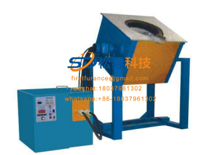
Small -type induction melting furnace
The picture shows the lifting induction melting furnace, all work is done on the level ground, and the operation is convenient and safe. This furnace is suitable for melting different kinds of alloys.
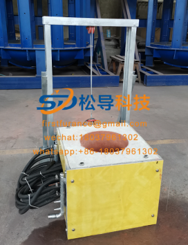
Lift type induction melting furnace

