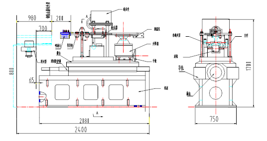
In the overall structural design of the machine tool, we consider that it should consist of the machine rail, slide, worm gear, struts, pre-clamping mechanism, guiding mechanism, upper mounting plate, induction heating system, etc., as shown in Figure 13:

Figure 13 Overall structure of the machine
The action situation is as follows: After the pre-centering clamping is completed, the slide cylinder push rod pushes the slide table to feed along the slide rail, and the clamping action is accurately performed to accurately position the rail. The sensor heats the rail end of the rail. When the induction heating is completed, the accurate clamping device is released, the slide cylinder push rod drives the sliding table to return to the spray position along the slide rail, and the sprayer starts to work on the rail end spray cooling. . After the cooling request is reached, the machine slide retracts to the original position along the slide.
For different types of rails, adjust the height of the sensor and the reference surface by adjusting the upper and lower nuts of the pole and the worm gear pair.
The following points are mainly considered in determining the position of the clamping mechanism:
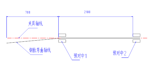
A: According to the left and right bending parameters of the rail ≤0.5 mm/1000mm , it is possible to install a pre-centering mechanism about 700mm inside the rail metal wire and another pre-centering mechanism at about 2100mm inside the rail metal wire. When the pre-centering mechanism is clamped, the left and right offset of the rail head can be reduced to less than 0.3 mm. As shown in Figure 14:

Figure 14 Rail left and right bending calculation diagram
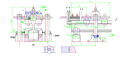
B: According to the upper and lower bending parameters of the rail ≤0.5 mm/1000mm , you can choose to place the lower pressure guide wheel at 300mm from the rail metal wire, as shown in Figure 15:

Figure 15 head assembly dimensions
It has a fine-tuning function, and it can also adjust the upper and lower gaps of the rail and the inductor to within the process requirements.
4.2, sprinkler design
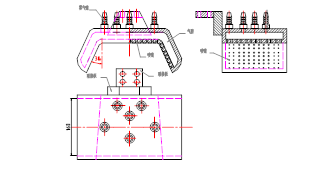
In the design of the mechanism, stainless steel material was first selected on the material selection to prevent rust from clogging the nozzle. It should also ensure that the medium flows smoothly in the shower cavity and the air pressure is uniform. And according to the profile of different types of rails, the nozzle on the side of the spray gas is kept at a certain angle with the part to be quenched on the side of the rail to ensure the quenching process requirements. Its specific form is shown in Figure 18:

Figure 18 Sprinkler diagram

